OFF topic! Yaesu FT710 (and others)

Hello again…

Until recently my radios were an Icom IC7300 and a Xiegu G90, The Icom I ever use via WFView.

Now I’m also the happy owner of a Yaesu FT-710, and I connect it directly to the QLog software. Until now I was using CQRLOG via IP from WLView into my Icom radio, and it was going great.

But the Yaesu , I find it a bit more comfortable to receive than the others. Less noisy And so now it’s mainstream radio. Sorry!

Actually, that’s not why I’m writing.
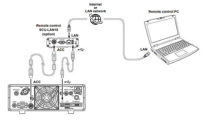
The radio (yaesu) has a remote control system with an added hardware, SCU-LAN10 that allows remote control, and also lets you see the waterfall (ugly yaesu waterfall).
It uses ports for audio and control, similar to ICOM, but without the additional hardware we have no access.
This software from Yaesu only exists for windows, and not for Linux. It may work via wine, or it may not.

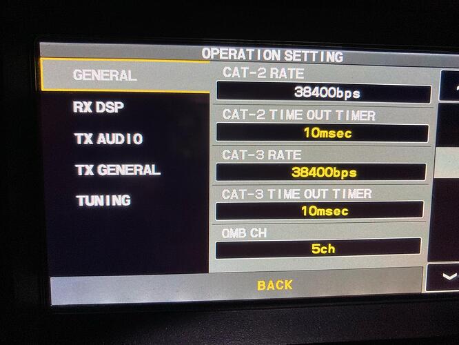
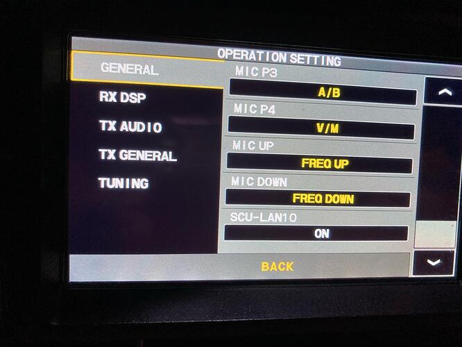
But I have seen something, which I think can be interesting, is that apart from 2 serial ports that generate the USB bus, if it is activated in the menu “operating setting” and GENERAL, SCU-LAN10 in ON, it activates a other device on the usb bus: a GPIO SPI/I2C bus, I don’t know if this can be interesting to control the radio. Attached is a syslog capture.

Maybe you could connect to this bus and “see” the yaesu from WFview?

Cheers!

If you can figure out how to get the waterfall out over serial (or SPI/I2C), then you would have a candidate for inclusion as we begin to write code for more radios.

I looked around the internet and nobody seems to know much about how to do it.

I just spoke to a colleague who has an FTDX10 and does not have the option to activate the SCU-LAN10 in the menu of his radio.
I’ve been looking at the connection manuals for the 3 yaesu radios that connect to the remote control hardware, and the FT710 is the only one that does it all with just the USB cable. The others use the ACC port.
Without knowing anything about how this device works, I think the FT710 is the only one of the three that includes an I2C bus.
When I have time and can go to the colleague’s house, I will try to find out if there is an I2C bus in the list of devices that appear when connecting the USB of a Yaesu FTDX10 or FTDX101, but I suspect that it will not be there.

I haven’t found any information on the internet about this either. But the truth is that every day more and more FT710 are sold. It would be good to find an economical way to be able to use the equipment remotely. Too bad I don’t have any programming knowledge, even so I’ll see if I can access the I2C bus or the gpio… I found some libraries but I don’t even know where to start.

I would guess the I2C and SPI stuff is for ancillary functions that they forgot to or couldn’t assign to commands over serial. House keeping things like power/standby/sleep functions and that sort of stuff.

The second serial port that appears is likely dedicated to the waterfall data. I’m just guessing here, but it’s a lot of data compared to the commands, and I could see them wanting it on a separate interface.

What you could try is enabling the SCU and connecting the SCU, and then making a connection to it. Then unplug the SCU and swap in a linux PC. Open that secondary serial port and see if any data are coming out. Dump any data to a file, and then share :slight_smile: Or maybe the thing detects the SCU unplug and stops streaming the data, who knows. Maybe it’ll stream data the moment you enable the SCU in the menu, it might.

Happy hunting,

–E
de W6EL

Well, continuing with the offtopic, I have reviewed the manuals of the two Yaesu hybrids and in both cases, in addition to the USB cable, they connect the ACC port.

also, and as my friend confirmed to me, the FTDX10, and I presume the same is the case with the FTDX101, They have no option to activate or deactivate the SCU-LAN10 in their menus.

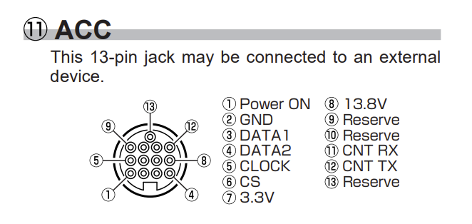
So, I understand that the function of the FT4222 port that is activated by switching SCU-LAN10 ON is to generate the equivalent data to the ACC port of the other two Yaesu SDR models.
So it would be logical to find the information that is in the ACC.
image

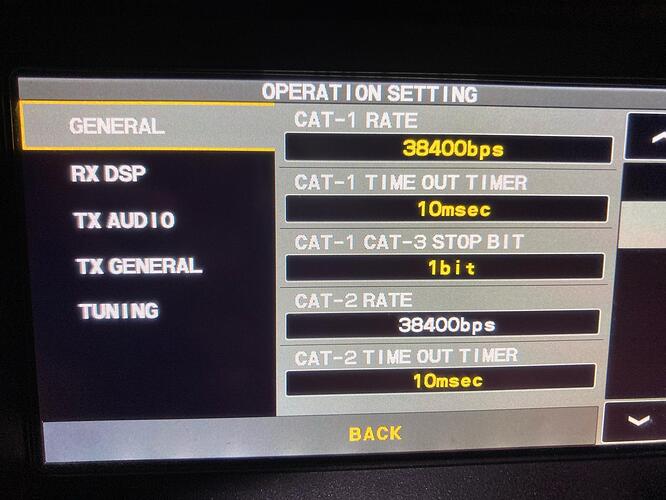
On the second serial port, the baud rate can be chosen in the menu, just like with port number 1.
By the way, there is a third serial port… although it doesn’t appear on the USB bus.
The FTDX10 has it with a standard 9 pin port, and I wonder if this third port is simply not connected anywhere and is only on the board, inside.

It always seemed to me that yaesu makes each device with a different group of engineers, and they don’t talk to each other. I’ve had an FTM100 and at the same time an FT70D, which are devices from the same era, with digital modulation. And I remember that the way to access the same digital services via RF was totally different in the two devices, and no menu looked alike. By this I mean that yaesu is a bit chaotic, and yes, this time, in my opinion, he got it right with the FT710 receiver, but I think he went on doing it, not knowing very well what he was doing or what hardware he would end up needing. And here may be the explanation of the third serial port that does not appear anywhere but in the menu.

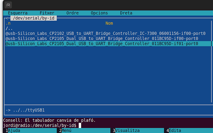
Here my list of usb, first is Icom 7300

Here you have the Yaesu 710 menu


another thing I’ve seen is that the serial ports don’t die when turning off the radio, the sound cards stop, and also the I2C/SPI. This means that the radio can be started via the serial port, which if it remains activated.
FLRIG manages to open or close the radio, via serial port, which confirms it, even if you choose FTDX10 instead of FT710, and we know that FTDX10 only has serial ports.

About the second USB port, I configured it in the QLOG and it seems to work exactly the same as the other one. As much as it also makes the same mistakes, both in the mode and in the frequency modification. Maybe they generate them to be able to have 2 programs at the same time connected to the radio, one on each port. I doubt very much that the waterfall data goes through there.

Today stop the search…

Very interesting! Two cat interfaces. A handy feature really.

I know the usual commands are pretty well-known.

If anyone knows how the waterfall happen, I’m all ears. Maybe there’s raw I/Q and the computer does the FFT?

My best guess is that you have to buy that $300 box because they were not able to complete the design with those features built-in. Schedule, cost, and engineering constraints likely lead to them making the box an external addition.

We do plan to eventually support other brands of radios, pending the discovery or publishing of their protocols.

—E
de W6EL

Hello Eliot, Jordi,

Thanks for letting me in to this discussion. I got some recent experience with FTDI chips and drivers, so i gave it a try and wrote a little c# program based on my Q&A sessions above. Here i share my findings so far:

@eb3am The radio hase 3 CAT interfaces, the 3rth is de real one at the acc port.

So far the guesses in my Q&A session seems to add up, summary:

  • The chip works in de mode zero, with one SPI and one other interface. (That is not used.)
  • They are marked as A and B, according the docs the SPI interface is at A.
  • I did a READ on the A interface with the default credentials and received a stream of bytes.
  • Wrote the bytes to a file.

Next: Read bytes with different credentials (clock speed, msb/lsb, databit length, buffer length).
Investigate the results and share the files here.

Imre
de PD2I

Morning,
My research had ‘some’ results:

using Iot.Device.Ft4222; // nuget package
using Iot.Device.FtCommon; // nuget package

configuration:

Select the device with description “FT4222 A”

ClockFrequency = 125_000,
// The SPI mode being used.
Mode = SpiMode.Mode0,
// The bus ID the device is connected to.
BusId = 0,
// The chip select line used on the bus. -1 if not used
ChipSelectLine = 1,
// The length of the data to be transfered
DataBitLength = 8, // 1 byte
// Specifies order in which bits are transferred first on the SPI bus.
DataFlow = DataFlow.MsbFirst, LsbFirst, MsbFirst
// Specifies which value on chip select pin means “active”.
ChipSelectLineActiveState = PinValue.Low

  1. Every 4096 bytes the data seems to repeat, so we read buffers with that size.
  2. When changing clockspeed and/or the amount of buffers read, the format of the content is the same.
  3. Tried with a dummy load and then at a buzzy band, the First 850 bytes (0000-1349) changes sigificant. Low values for high levels and vica versa.
  4. At 06A4 a new Block of data starts, ending at 18FB (Gues: bandwith waterfall)
  5. At 1B65 a small piece of data, that is the same in all frames (config?)
  6. Every buffer ends with 16 times FF

WARNING: Do not send bytes thru the interface! In the examples programm 2 byte were send, it screwed up my rig. Luckely a reset repared it.

I have no idea if its i/q data, visual data or else.

Download: C# programm;

in ‘\bin\Debug\net6.0-windows\Samples’ many recordings

https://www.livep2000.nl/ft710interface.zip

I hope someone can make something out of it.

Imre